Enhance your privacy and security with our advanced cell phone signal jammer. This cutting-edge electronic device employs the same frequency as mobile handsets, effectively blocking the transmission of signals between your phone and the base station. Our jammer boasts powerful interference capabilities, ensuring uninterrupted protection against networks like 4G, 5G, UMTS, 3G, CDMA, GSM, and PHS. Discover the most straightforward method to craft a mobile phone signal blocker tailored for 2G network blocking. For superior signal jamming requirements, explore our homepage for advanced options. Safeguard your communications today with our trusted signal jamming solutions.
- DIY Cell Jammer – Essential Components for Sale
- Cell Phone Jammer Circuit: Optimized for Efficiency
- Cell Phone Jammer: Working Principles
- Mobile Freq Jamming Calc: Optimize Signal Blockage Efficiency
- What Jammer? Note
DIY Cell Jammer – Essential Components for Sale
| Build your own signal jammer with precision components! | ||||||||||||||||||||||
|
Cell Phone Jammer Circuit: Optimized for Efficiency

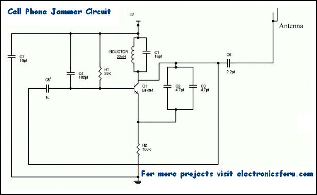
Cell phone signal jammer circuits are comprised of three pivotal subcircuits: an RF amplifier, Voltage Controlled Oscillator, and a Tuning circuit. These three components, when integrated seamlessly, result in an efficient and robust jamming solution.
- RF Amplifier: Boosts the signal’s power.
- Voltage Controlled Oscillator: Generates frequencies to block.
- Tuning Circuit: Fine-tunes the jamming frequency.
Cell Phone Jammer: Working Principles
The amplified signal, filtered by capacitor C6 to block DC and allow only the AC component to pass, is then transmitted through the antenna. When transistor Q1 is turned on, the tuned circuit at the collector also activates. As the capacitor charges, it releases its energy through the inductor, creating a magnetic field. As the current flows through the inductor, it stores magnetic energy corresponding to the voltage across the capacitor.
At a certain point, the inductor reaches its maximum charge, and the voltage across the capacitor drops to zero. This is when the magnetic charge through the inductor decreases, and the current reverses direction, charging the capacitor in an opposite or reverse polarity. This process repeats itself, with the inductor eventually discharging the capacitor back to zero. This cycle continues until internal resistance is generated, and the oscillations cease.
Prior to reaching capacitor C6, the RF amplifier feed is supplied through capacitor C5 to the collector terminal. Meanwhile, capacitors C2 and C3 generate random pulses or noise at the frequency generated by the tuned circuit. The RF amplifier boosts this frequency, combining it with the noise signal generated by capacitors C2 and C3. The combined, amplified signal is then transmitted, effectively disrupting or jamming cell phone signals within the jammer’s range.
Mobile Freq Jamming Calc: Optimize Signal Blockage Efficiency
- F = 1 / (2 * sqrt(L1 * C1)) – This formula determines the frequency (F) based on the inductor (L1) and capacitor (C1) values. Adjusting L1 and C1 allows for generating specific frequencies to block.
For instance, if mobile phones in your area operate at 450 MHz, you must generate a 450 MHz signal with noise to block them. This disrupts the phone’s ability to distinguish legitimate signals, effectively jamming communication. Here, 450 MHz serves as the tuning frequency. cell phone jammers for other frequency ranges follow similar designs, albeit with adjustments to the circuit components. However, these jammers have limited range, typically effective within 100 meters due to the signal’s weakness.
What Jammer? Note
Important : While this signal jamming circuit boasts the ability to disrupt transmissions within a 100-meter radius, it’s crucial to be aware that its usage is outlawed and prohibited in numerous countries. Additionally, this technology is commonly employed in TV transmission and remote-controlled toys. If you encounter any operational issues, consider adjusting the resistor and capacitor values in the circuit using the provided formula. However, please note that the power supply for this circuit must not exceed 3 Volts for optimal performance and safety. Be mindful of legal regulations and responsible usage.
